A few thingz
Joseph Basquin
15/02/2026
#electronics
MIDI Quantizer: my one-week journey into the Arduino world to build a MIDI event processor
Day 1: the idea
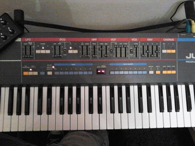
Sometimes I play and record synthesizer for a song I'm producing, but somes notes here and there are out of rhythm... I wish they had been perfectly in the rhythm out-of-the-box! Indeed, for electronic music based on loops, it can be annoying to have out of sync notes (well I agree that on some tracks, it's cool to have a not-perfect timing that brings "life", but not on all of them).
Of course, you can always use Ableton Live's "Warp" feature to correct the timing of the notes, or alternatively record first in MIDI, MIDI quantize, and then send the quantized MIDI performance back to the synth. But having to stop playing and go to the computer is sometimes not what you would have liked.
Idea: let's build a MIDI device that takes all incoming notes arriving on MIDI IN, quantize them (i.e. align them on a grid based on sync messages, for example a 1/16 notes grid), and send them to the MIDI OUT. All of that, realtime!
Day 2: get some electronic parts
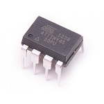
I first needed some electronic parts to do that: a breadboard, an Arduino Nano, some resistors, capacitors, an optocoupler 6N138 (very often used for MIDI circuits) that I still had in my drawers, and a small ATtiny45 chip kindly provided by the cool local Fablab team.
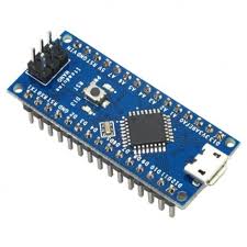
Then I learnt how to do a basic Arduino program (with the usual setup and loop functions) on an Arduino Nano. If you have a Nano clone like me, you'll need to install the drivers (CH34x_Install_Windows_v3_4.zip) to make it work.
The next step is to be able to use the Arduino Nano as a programmer to upload code on a bare ATtiny45 chip. The interesting thing is that you can remove the Nano at the end, and your code will still be running on this small 8-pin standalone 1$ chip! To do that, first open the "Arduino as ISP" sketch in Arduino IDE, and upload it to the Nano. Then connect the ATtiny45 to the Nano using this schematic, use "Programmer: Arduino as ISP", and "Upload using programmer". In real life it takes a few hours to get all these things working, but more or less that's the summary.
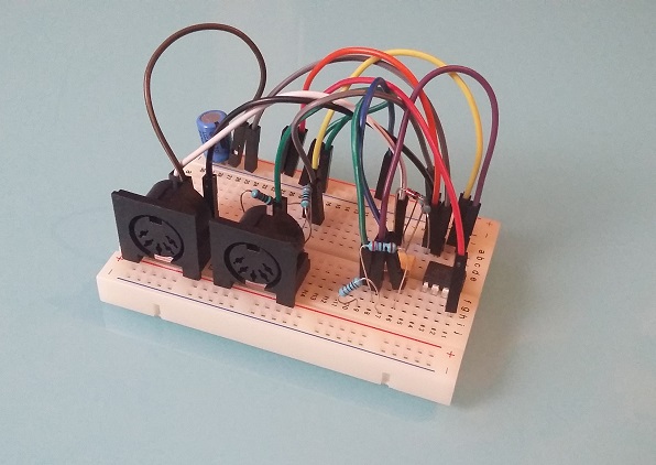
Then I assembled a basic well-known MIDI IN and MIDI OUT circuits, routed to the pins of the ATtiny. I wrote some test code to send MIDI messages at 31250 baud and it worked!
An other awesome thing I wasn't even expecting: this device will require no 9V battery, no AA battery, no 9V adapter... Wait, are you saying it will not be powered? The answer is: MIDI powered! The chip consumption is so small that it can be powered by the MIDI IN cable itself (inspiration here), the only component needed for this is a large-enough capacitor, something like 33 µF.
Day 3: it works, now let's make a real PCB of it
Since it works on the breadboard, I decided to learn how to make a PCB that will be eventually manufactured in China (I phoned various local electronic companies in France: nobody produces PCB locally anymore...). For this purpose, I installed Eagle software, discovered how to find components (not easy to find them in the libraries at the beginning) and to do a simple schematic. Then go in "Board" mode and use the "Autorouter" to automatically place components on the board.
A couple of hours later, I sent the board Gerber files to Seeed China who will make the PCB for the crazy price of 5$ (for 10 units, amazing!).
Day 4: work on the code, and discover the software serial madness
Decoding serial port input raw bytes into useful MIDI messages is not as easy as it seems: certain MIDI messages are 1-byte long, some other are 3-byte long, etc. so I spent some time achieveing to do that.
I then discovered that receiving and transmitting bytes on a serial port (MIDI is just serial after all) is not an easy task if you have to do it via software. But wait, why do it via software? Answer: the ATtiny45 does not feature a UART hardware serial, so it's up to the software to do it. All works well when you play only a few notes per second on the keyboard, but things are more difficult if you receive more than 10 MIDI messages per second on the MIDI IN (and this is the case: BeatClock messages used for synchronization use 24 messages per beat): the chip is lost, and the bytes read and sent are ... simply garbage! So I tested various software implementations: NewSoftSerial, NeoSWSerial, AltSoftSerial, etc. but as of today, none of them solved the problem of being able to read and transmit bytes on the serial port at the same time with an ATtiny45, at 31250 baud.
Day 5: let's test with a chip that has a real serial port
I should maybe use a chip that has a real (hardware) serial port. An option would be the ATtiny4313 (20 pins), but I don't have any.
I then tested with an ATmega328p (thanks to Julien!), taken from an Arduino Uno. It works great out-of-the-box: the hardware serial does miracles, and there is no more issues, no more grambled MIDI messages!
Now I wanted to put this ATmega328p standalone on a breadboard, but it stopped working. Reason (discovered a few hours later): this chip was internally configured to use an external crystal clock, that I did not have. So you have to modify its "fuses" to make it work with its internal clock at 8 Mhz. Working again!
Only problem: the PCB that is currently being made at the factory has a slot for a 8-pin ATtiny, and now I need to use a 28-pin ATmega, oops! I'll figure out this later, and I'll use some wires for this v0.0.1 prototype.
Day 6: do nothing
Day 7: PCBs arrive at my door
(after the week-end)
Now the parcel finally arrived, after a long trip from Shenzhen, China.

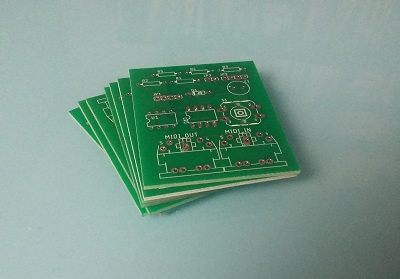
Let's assemble the components:
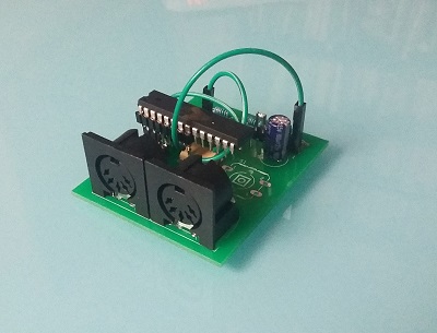
(It was a bit difficult to host the 28-pin chip on a PCB made for a 8-pin chip, but anyway... version 0.0.2 won't have these cables anymore).
Surprise, it works!
The "MIDI Quantizer" device is ready to be used :)
Edit: I've now done it with a 20-pin ATtiny4313, so only 1 wire is needed:
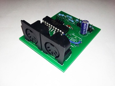
I assembled two units, one of them was working straight away, while the second seemed to have difficulties sending MIDI to some synthesizers (some synths reacted with "Illegal Data" message). I suspected the internal 8 Mhz clock to be not perfectly calibrated. So I re-uploaded the code with a internal-1 Mhz clock setting, and then it worked. Might be a good idea to add a crystal oscillator for next version of the PCB.
SamplerBox - a hardware sampler (to be continued)
This is in my Top10 biggest projects.
For many years, I had been looking for a small portable inexpensive sampler that can be used to play a good 1 GB piano sample set (with many velocity layers and supporting sustain pedal), a 500 MB Rhodes piano sampleset, drums, etc. and all sorts of sounds.
There was nothing like this on the market, but instead:
-
expensive samplers or expanders (800€+) that can do all of that, but they usually are not very portable
- cheap samplers like the Korg Volca Sample or the Akai MPX16, but they only offer a few MB of sound, and usually support no velocity layers, the loading time can be very long, etc.
So I started brainstorming about this (this was my first sketch, I always search ideas with a pen + paper):
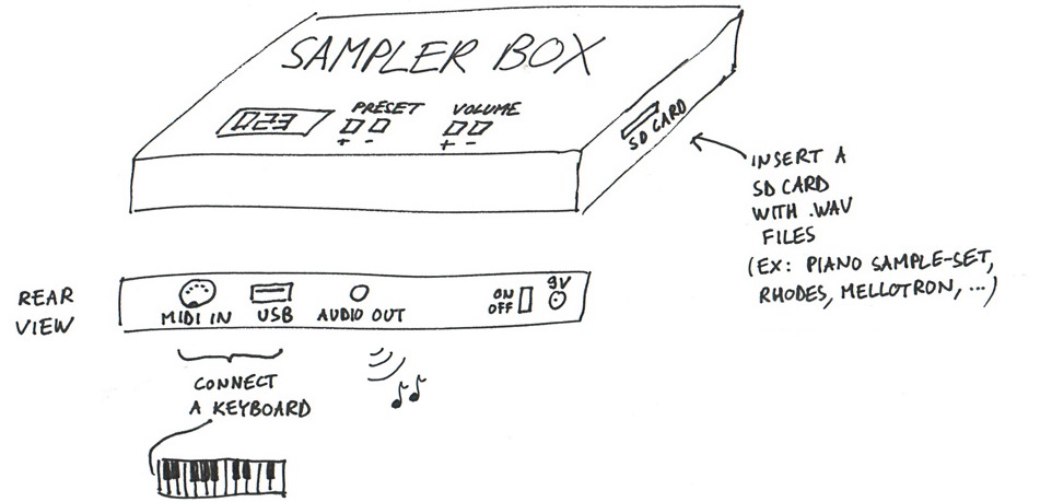
... and came to the idea that this could be possible with a Raspberry Pi. I then started to code a mixing engine in Python. Everybody told me "This is impossible, you won't be able to have a decent polyphony with Python, it's not fast enough...". The challenge was appealing for this reason and also because the only solutions available on Raspberry Pi at that time were 6-voice polyphony software samplers.
I spent days on this, and finally released both open-source code and hardware (rough) schematics:
Here is the blog: https://www.samplerbox.org/blog
I was happy to achieve a polyphony of ... nearly 100 voices at the same time, so my mixing engine in Python+Cython was not too bad ;)
Then it's a long story, many people contacted me, a commmunity growed on the forum (I should do a post about the software powering the forum, it's handmade too), etc.
(to be continued...)
